260118 - Update for 2026
MD26
The main priority is to clear some of the technical debt from past years. The lack of documentation and calculations were a issue at comp as well as for new members.
Goals for 2026 (Technical):
- Documentation
- Messy wiring
- Use better connectors (Panel mounted connectors)
Gals for 2026: non tech
- Training up skilling and retention
Coming from MD25, there are many things that will be improved. The main issues identified are associated with reliability of the system as well as rules compliance.
There are a few items that will be the main focus for MD26. The priority is the accumulator redesign. Although we passed scrutineering, many of the aspects of the accumulator are not ideal. For example getting each segment in and out wasn't user friendly as well as the many modification made to the accumulator at competition. There are plan on changing the configuration of the Enepaq modules. Currently the configuration of a segment is 22s 4p. However this configuration creates very blocky segments or a super long segment. Both of these aren't the best configuration. This creates challenges with mechanical integration. These could be mitigated but it increases the complexity of the design, making it difficult. The main limitation the design is the Orion BMS, only allowing up to 4 different segments. To mitigate this issue, we are looking into using the Enepaq TinyAFE. This will function as cell managment units (CMU) attached to each segment. Then the next challenge is the development of a battery management unit (BMU). The TinyAFE requeires a custom BMU or a existing BMU that needs to be translated to work with the TinyAFE communicatons protocol. Currently the two potential options are to develop our own or use the existing
The main issues with reliability was due to MD25 being the first EV, these issues will always appear and can be mitigated with more time. This means when things get build, do it properly for the first time, as most likely it will end up in the car even if it isn't done well.
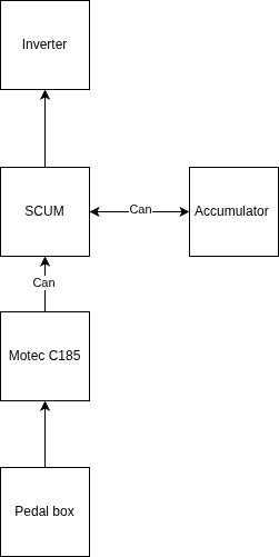
One of the main things to improve next year from the low voltage side is using the Motec C185 dashboard. The dashboard is very powerful with many features. The plan is to use it as a main node in the vehicle architecture, receiving inputs such as APPS and doing prepossessing as well as logging all the sensor data. The C185 is significantly more powerful that most dashboard that other teams use and could handle most very basic ECU functions (At least in the MD25). Then any other data will be communicated over CAN to the SCUM.
In addition to this, the SCUM needs to be updated, the Amphenol connectors are only rated to 250V, meaning the TSAL circuit will need to be moved to a independant board with rated connectors. This means there will need to be a minor SCUM redesign. More GPIOs are needed as well, reading values from the shutdown to know the state of the car. This will be done on PCB, as other teams need to do it off board on their ECU, but the SCUM is a integrated system.
In addition to this, there is a ready to move light rule in the 2026 rules, however unsure if it will be our rules this year.
Currently I am also in talks with SBG system to get a INS (Inertia navigation system). This would be used for data logging/ vehicle dynamics analysis but most importantly for traction control. This will help with points in design as the decsions that we make can be justified with real data. This means that basic vehicle dynamics model should be made. UQR has a very advanced model developed for a thesis to do this. This means that every change they could make to the car can be seen in a measurable point increase. For our purposes a point mass system will suffice.
The traction control system will involve having a board that will process all the signals and send it to the SCUM. The most important thing that we want is the true vehicle ground speed. If our true vehicle ground speed is slower than the motor speed it means that there is slipping in the wheels. To prevent this, the best way would be to modulate the throttle signal to be lower (EV.3.1.3). This would mean setting the target RPM to be just a bit higher than the current RPM. It is acknoledge that we are using current control for the inverter, meaning that we can't set a target RPM, but using the INS can can calculate the values required to change the speed by x amount. Another simpler method that might be more finicky is to hard code PID values through testing to get the proper traction control values.