BSPD current sensor
The BSPD is aan partintegral component of the shutdown circuit. Its jobfunction is to detect whensituations there is simultaneouswhere braking and high power output.usage Thisoccur meanssimultaneously. thatIn other words, if the driver could beis accelerating and braking at the same timetime, andthe itBSPD will triptrigger the shutdown circuit, switchingturning off the car.vehicle. As a importantcritical safety aspectfeature, init is essential to test the BSPD to ensure that the system functions correctly.
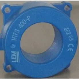
The system detects power output using a Hall effect current sensor, which measures the current passing through the wire it surrounds.
During the technical inspection, it is necessary to verify that this part of the shutdown circuit itoperates needsas tointended. beHowever, testedtesting to prove that the system works. The method to detect the power output is through a hall effect current sensor, measuringrequires the current thatsensor isto passingmeasure through.actual Tocurrent testflow. This can be done by jacking up the car and spinning the wheels in the air and pressing the brakes, however this withoutmay drivingnot isbe difficultfeasible. and this check procedure occurs before driving is allowed. This meansTherefore, a solution needs tomust be developed to simulate current passing through the sensor for testing purposes.
 A hall effect current
 going through when needed for tech inspection.
sensor
The BSPD must Open the Shutdown Circuit EV.7.2.2 when the two of these exist:
• Demand for Hard Braking EV.4.6
• Tractive System current is at a level where 5 kW of electrical power in the DC circuit is delivered to the Motor(s) at the nominal battery voltage
- EV.7.7.2
This project will focus on the TS power level, where the BSPD check is already handled by the SCUM.
Implementation
The current sensor measures current passing through,through and is independent of the voltage, however the rules dictates for a power draw of 5kW. Power is comprised of current and the voltage. This means to simulate the power of 5kW through the tractive system, a certain amount of current needs towill pass through.through the current sensor.
To calculate the current for 5kW, we can P=IV. Where V is the nominal TS voltage. This is the current that needs to pass through the current sensor. However this value is usually fairly high, infor theexample 10 amps range which isn't always feasible to pass through the current sensor. However there is a solution to this, by wrapping wire around the current sensor multiple times, the current sensor will be able to detect the current passing through as increasing. eg. 1 amp looped 10 times will measure 10 amps.
To supply the current the GLV power system will be used. So to calculate the value of the resistor required we need to use V=IR. Where V is the nominal voltage of the GLV power system (12v). It is possible to pass 10 amps through another wire but consider the practical aspect of drawing so much current through the GLV battery.battery and wire. The main decisions that you will need to make is the resistor value and the number of turns around the current sensor.
Important considerations in component selection:
- Power rating/ current rating of switches and wires
- Size of components
- Easy of maintenance and verification
- Size/ packaging
Bonus points:
- A good write up on how you designed it
- Write a python program to do all the calculations.