AEGIS Board
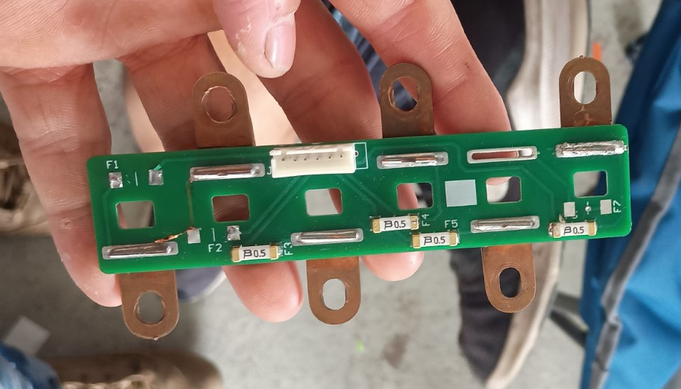
The Automated Energy Governance & Intelligent Storage (AEGIS) Board sits on top of each segment. The goal of this board is to integrate many systems together onto one board for convenience by simplify wiring to improve reliability. All the wiring is handled on the board, reducing possible human errors such as incorrect wiring which can have serious consequences. The integration of the AEGIS board has been proven successful on MD25, however many changes are required resulting in a redesign. This is a common design approach taken by many teams.
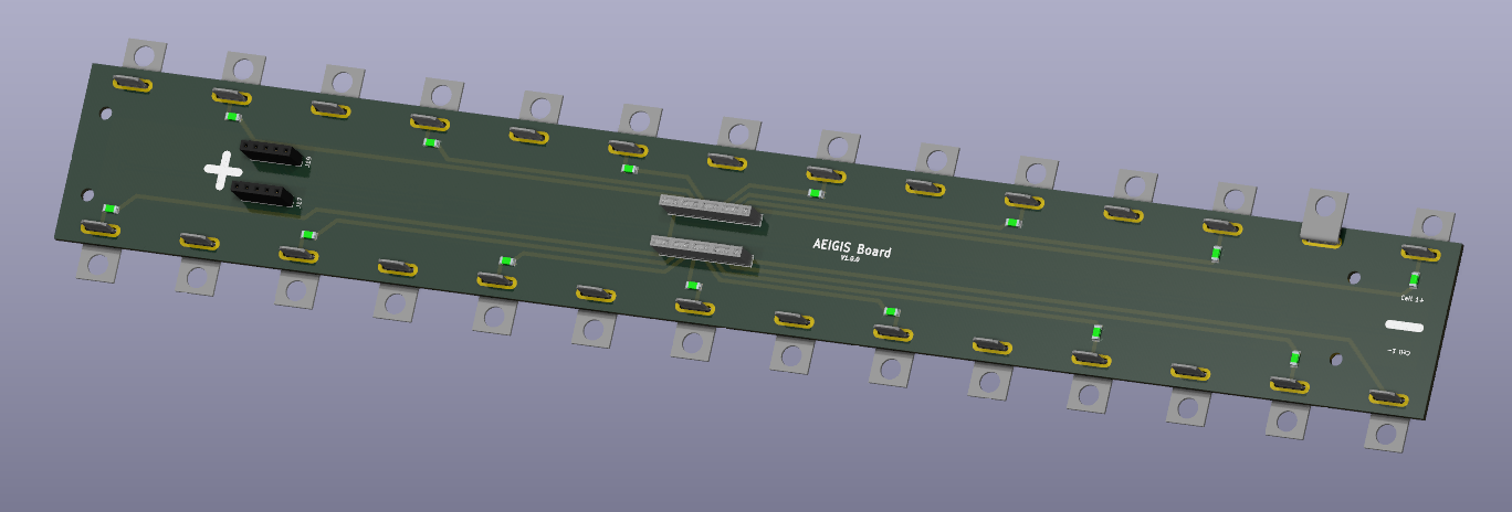
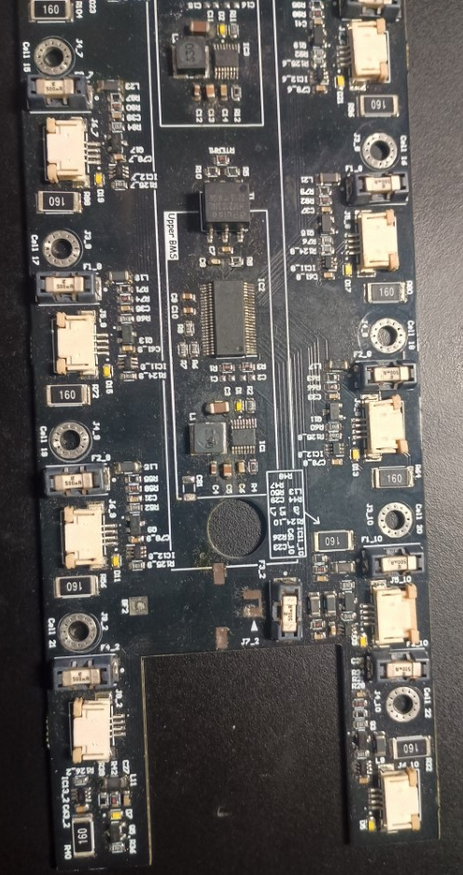
Initial prototype of the AEGIS Board for MD26 dated 260221.
The AEGIS is a passive board meaning that it doesn't have any active components (eg. MCU, transistors) and it doesn't do any processing, acting as a front end, collecting and aggregating all the measurements for the BMS and CTMS.
The AEGIS board handles:
- Cell tap voltage measurements for the BMS
- Fusing of the cell taps
- Temperature sensor aggregation.
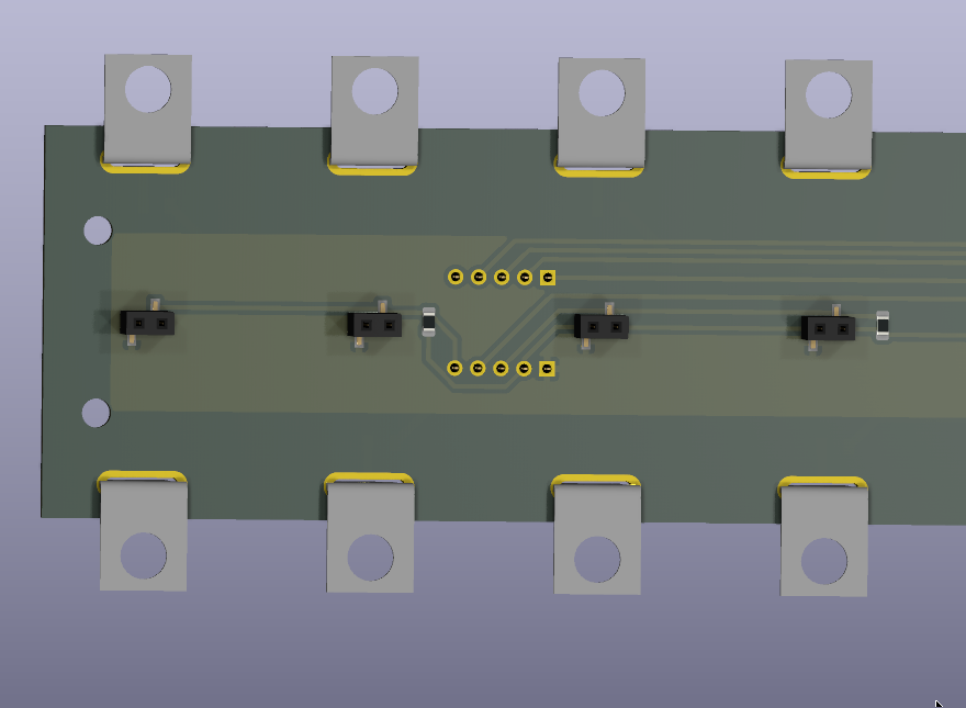
The cell tap connector is the central connector, connecting to most of the cells. This allows for measurements to be made by the BMS and also allows the BMS to balance each cell.
Each cell connection also contains a fuse, this is to comply with EV.7.4.3. The fuse values are Little fuse 0437001.WRA. These are 1A fast blow fuses. The purpose of this fuse is to protect the downstream system from the BMS, the BMS itself has its own fusing internally mainly to protect itself. This doesn't prevent issues from occurring downstream, eg. a dropped screw shorts two of the connections on the board, or if the wiring insulation is damaged and causes a short between two cells. This is a requirement for rules but also good practice.
In addition, as required by FSAE rules and best practice, cell temperatures should be monitored as the temperature can indicate issues ahead of time and can allow the vehicle to be shutdown safely, eg. thermal runaway. This is done through using the internal temperature sensors on the Enepaq Modules through 2.54mm pitch connectors located on the bottom of the PCB. See below. This then allows the CTMS to sit on top of the board, to aggregate and process all the measured temperatures.
Implementation by other teams
University of Melbourne Racing team 2025 competition
Academy Racing Team 2025 competition
University Of Queensland Racing 2025 Cell Management Unit
No comments to display
No comments to display