CTMS
Problem
The cell temperature monitoring system is a module with each segment that will monitor and report all the temperatures to the Orion 2 BMS. This is part of the AMS to monitor cell temperature to make sure that there aren't any issues, for example thermal runaway. In MD25, the method to monitor was NTC thermistors placed near the negative terminal on the AEGIS PCB near the bus bars. This method passed accumulator scrutineering, however this isn't the best way to monitor temperatures and could flag us this year. The issue with this was that this meant that each thermistor couldn't actually monitor the module temperature. This is mostly (its very iffy and car be argued both ways) rules compliant, however the rule mainly for team who are manufacturing their own modules to be able to mount their thermistors near the negative terminal.
In addition to this, the current implementation was unreliable, hand soldering 0402 component connected to a ground plane resulted in low levels of reliability from the thermistors, causing many faults that needed to be manually reset.
Requirements
Rules
The BMS must measure the temperatures of critical points of the Tractive Battery
- EV.7.5.1
Cell temperatures must be measured at the negative terminal of the respective cell
- EV.7.5.3
The temperature sensor used must be in direct contact with one of:
• The negative terminal itself
• The negative terminal busbar less than 10 mm away from the spot weld or clamping
source on the negative cell terminal- EV.7.5.4
For lithium based cells,
a. The temperature of a minimum of 20% of the cells must be monitored by the BMS
b. The monitored cells must be equally distributed inside the Tractive Battery Container(s)
The temperature of each cell should be monitored- EV.7.5.5
Multiple cells may be monitored with one temperature sensor, if EV.7.5 is met for all cells
sensed by the sensor- EV.7.5.6
Temperature sensors must have appropriate electrical isolation that meets one of the two:
• Between the sensor and cell
• In the sensing circuit
The isolation must consider GLV/TS isolation as well as common mode voltages between
sense locations.- EV.7.5.7
Spirit of the completion
The goal of these rules is to ensure the safely of the accumulator from temperature related faults. Lithium based batteries can enter thermal runaway. Thermal runaway is a dangerous, self-sustaining chain reaction where increasing temperature causes faster chemical reactions, generating even more heat, leading to rapid temperature and pressure spikes, potentially causing battery fires or explosions, common in lithium-ion batteries. The goal is to fault the accumulator before it becomes a issue, preventing such incidents from occurring early through monitoring of the cells. The goal would be 100% monitoring as something like a lose bus car connection can cause heating that is isolated in a local area.
Design overview
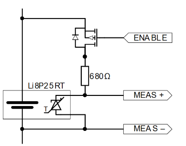
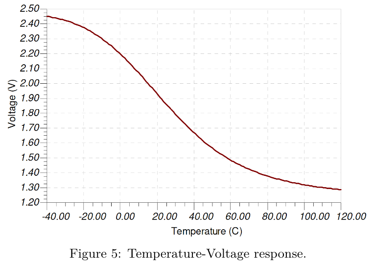
The solution to this problem is using the build in temperature sensors in the Enepaq modules. These are special temperature sensors which can be through of as a temperature dependant zener diode. This means that depending on the temperature it will have a voltage drop associated with it. The Enepaq modules have multiple temperature senors and only reports the highest one. To meet EV.7.5.7 the each temperature sensor will be powered with a isolated supply for each segment. So the segments will share the same power that is isolated from the GLV power system. The Orion BMS has a datasheet to explain how to communicate to it over can, so a isolated can module will be required. That is a basic overview so there will be a module for each segment as well as one board for isolated can communications.
Taking with UNSW Redback their configuration was to have 3 - 4 of the temperature sensors in parallel. Technically all the cells can be monitored with all of them in parallel because of how the Enepaq temperature sensors work. But the issue this with is in the event of a failure in the temperature sensors the minimum number of cells are no longer monitored. This method balances the use of ADCs with a safety factor to make sure the system will be functional and rules compliant.
Taking inspiration from UNSW Redbacks.
Development plan
Test manually reading data from Enepaq module temperature sensor
Prototype a PCB development board with a stm32G0 to read values, this board will include a digipot to work with the Prohelion BMU.
Package
No comments to display
No comments to display